
Search all blogs
Latest posts
-
 Masking Tape: Uses, Types & How to Choose the Right One27/04/2026Read more
Discover our complete masking tape guide covering die cut, high temp masking tape, automotive and specialist tapes....
-
 Coach Screws Guide: Sizes, Uses and Outdoor Fixing Advice20/04/2026Read more
Complete guide to coach screws, including sizes, timber applications and outdoor fixing advice. Ideal for sleepers,...

Manufacturing Processes
Moulding Processes
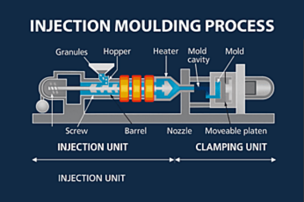
Injection Moulding:
Injection moulding is a manufacturing process used to produce complex and precise parts by injecting molten material into a mould cavity that has been shaped to match the desired final product. The material, typically plastic, metal or rubber, is heated until it becomes fluid, then forced into the cavity under high pressure. Once inside the mould, the material cools and solidifies, taking on the shape of the mould before being ejected as a finished component.
This process allows for the creation of both solid parts and intricate multi-faced shapes, depending on the mould design. The method can use a variety of materials, including thermoplastics, thermosetting polymers, and elastomers, allowing for multiple designs and applications for the same shaped part.
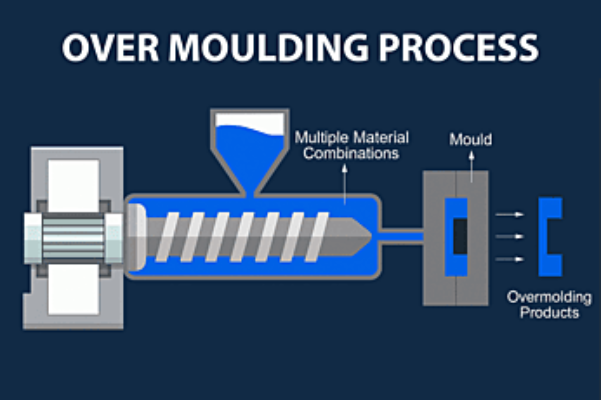
Over Moulding:
Over Moulding is a specialised variation of the injection moulding process, designed to create combined parts with multiple materials. Unlike injection moulding, over moulding requires a second component, often made from metal or plastic, to be placed into the mould before injecting the molten material around it. As the moulten material solidifies it forms a strong bond with the insert part. This is done to increase structural integrity or functionality.
This process is widely used in various industries to improve a products durability, grip and ergonomics. Common parts that use over moulding include bolt on plastic feet for furniture, tool handles with a rubberised grip and medical devices that require a combination of soft and ridged materials. A common everyday tool that is over moulded would be a screwdriver with a rubber grip.
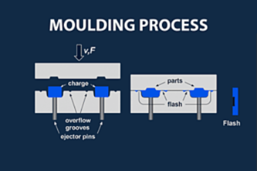 Compression Moulding:
Compression Moulding is a commonly used manufacturing process that is used for shaping materials like rubber and plastic. This method starts from the raw material being placed on the lower half of a heated mould cavity. The upper half is then lowered towards the part which starts to apply high temperature and pressure. This forces the material to form into the desired shape.
Compression moulding is a valued process due to its minimal waste and high durability and strength parts. It is used most frequently to make components such as gaskets, seals, and electrical insulators.
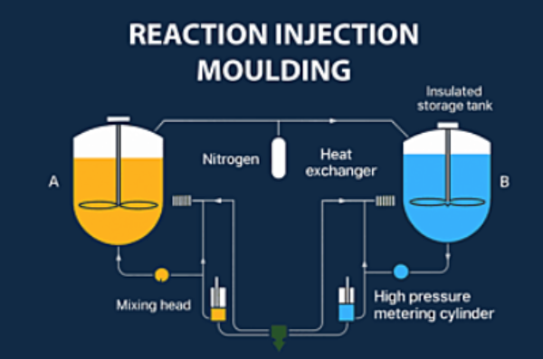 Reaction Injection Moulding (RIM):
Reaction Injection Moulding is a manufacturing process used to create complex plastic components. It involves mixing two or more reactive monomers before injecting the mixture into the mould. Once the mixture is within the mould a chemical reaction takes place and begins the polymerization which solidifies the plastic mixture into the desired shape.
RIM shares similarities with injection moulding however, the key differences are based in the temperatures and pressure applied to the part with RIM requiring less pressure and lower temperatures. This makes the process suitable for producing large lightweight parts. A drawback of RIM is the fact that the process takes more time than compared with injection moulding due to the time taken for polymerisation to take place.
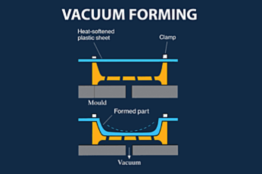
Vacuum Form:
Vacuum moulding is done by placing a thermoplastic sheet over a mould and heating it until it becomes pliable. Once the sheet is softened it is pressed down over the mould and then a vacuum is applied to remove the air between the mould and the sheet. The external pressure from the atmosphere causes the plastic to form more accurately over the mould creating the desired shape. The part is then cut out of the sheet using a stamp press, this can be done on the same tool or, more commonly, it is done on a separate tool.
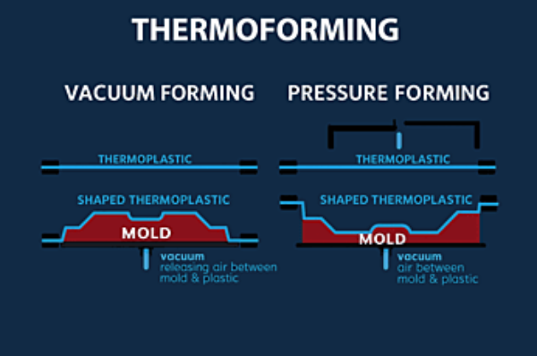
Thermoforming:
Thermoforming is a versatile forming method, similar to vacuum forming, that starts by heating a sheet of thermoplastic until it is soft and then placing it over a mould. Thermoforming uses several different forms of pressure in order to make the part including compressed air and mechanical forces to ensure that the parts details are clear and to improve the structural integrity.
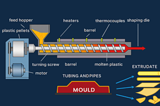
Extrusion Moulding:
Extrusion moulding is done by forcing molten material through a pre-defined shape which produces materials with a tubular or rod like profile. This is like injection moulding but does not use a cavity to mould the part but instead uses a die to create a continues profile with a consistent cross-section. This material is continuously extruded and cut to length after being extruded.
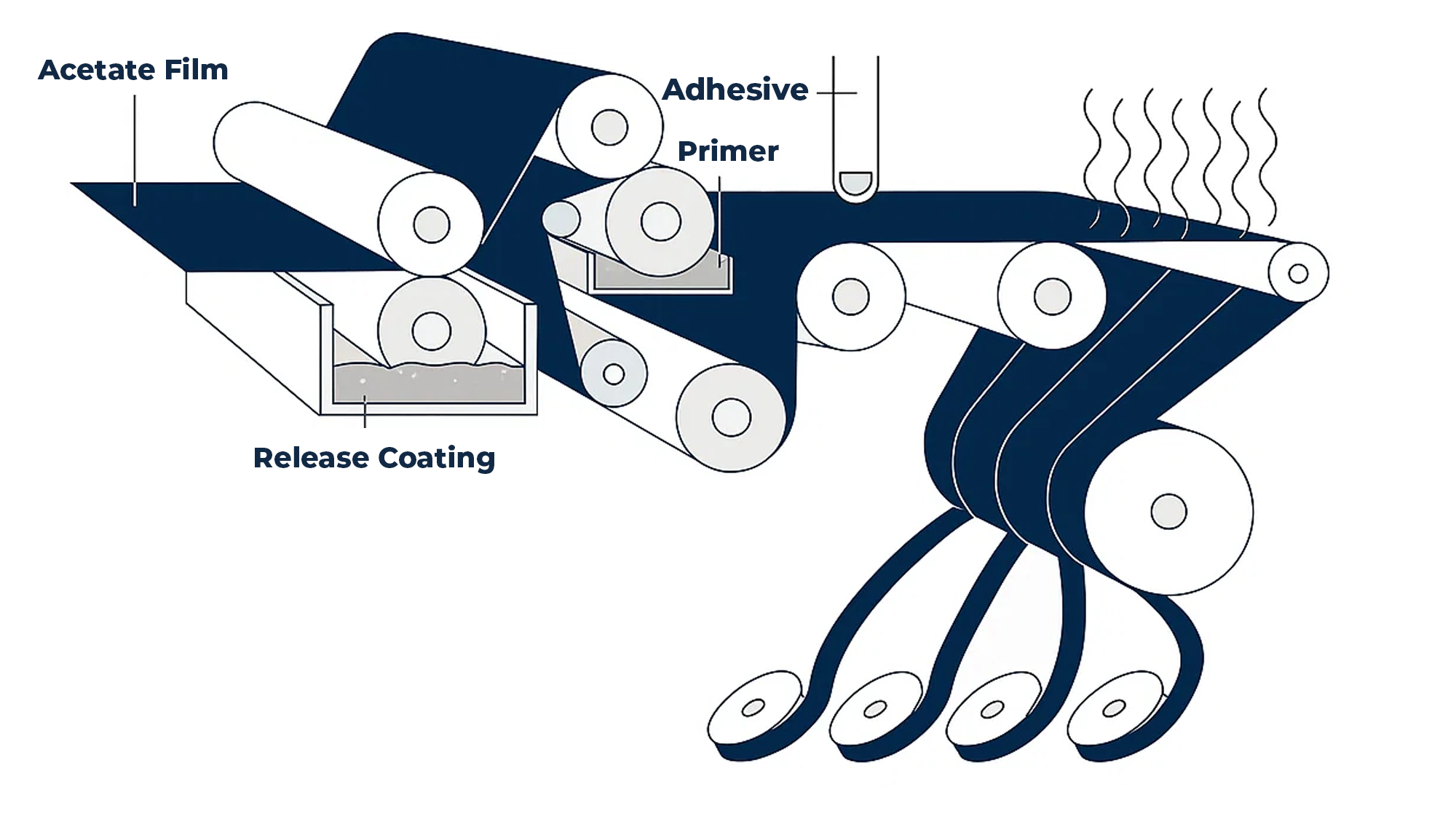
Tape Manufacturing:
Tape manufacturing has several steps. These steps remain mostly the same no matter what type of tape is being produced. The first thing to be produced is a substrate (Base part of tape) which is extruded out. While the substrate is being extruded the adhesive is made simultaneously, the adhesive is then layered onto the substrate sheet and rolled onto a core. These cores are a large in length but are cut down to size after the tape is attached. The materials used within the substrate and adhesive are changed depending on the material properties that are desired.
Additive Processes
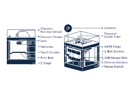
FDM (Fused Deposition Modelling):
FDM 3D printing is a widely used 3D printing method that builds a part by layering heated thermoplastic filament according to G code that has been programmed from a slicing software. The software is used to alter settings such as layer height, wall thickness and infill percentage. The process begins with a reel of thermoplastics, such as PLA, ABS, or PETG, being fed into the printer head through boden tubes. Within the print head the filament is heated to a precise temperature (this is decided within the slicing software or can be left default) to melt it before being extruded through the nozzle, this ensures a controlled deposition of material. The print head moves in accordance with the file that has been uploaded this allows the print head to bond the new layers to the older one. As the material is deposited, it begins to cool down quickly until it has solidified. This ensures that the part can maintain structural integrity while being printed. Once the print has been completed, extra steps such as removing supports or smoothing the part may be necessary to refine the part.
FDM printing has a wide variety of materials that can be used each with their own material properties. This includes flexibility, strength, or heat resistance. The technology is also rapidly improving allowing for better quality prints and more material options.
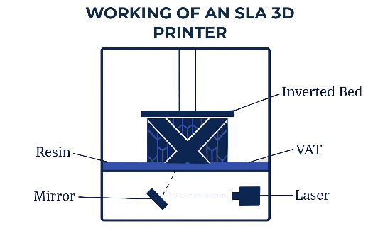
SLA (Stereolithography):
SLA printing is a modern and precise process for fabricating objects using resin. This method uses lasers or UV light to selectively cure the liquid resin layer by layer into the part. There are many different resin types each with different material properties such as, tough, and impact-resistant to flexible or clear resin options.
After printing the part, it must go through the post processing stage. This is where the print is first removed from the printer and placed into an IPA (Isopropyl Alcohol) solution wash. This process is done to remove any uncured resin that may still be on the surface of the part. This process can vary depending on the printer that is owned as some come with a wash where the whole print bed is placed into it, whereas others require the part to be removed from the print bed and placed into the wash separately. This step is done to ensure that the finish, dimensional accuracy, and details are kept when curing the part.
The next process is placing the washed part into a UV oven where the part is exposed to intense UV radiation and elevated temperature to increase the rate at which the resin is fully cured. While the resin would have been partially cured during the printed process the final stage in the oven is where the final curing takes place and increases the parts strength and durability. An alternative option for curing a part but not hugely recommended is leaving the part in direct sunlight for an extended period of time. Although his will cause the resin to fully cure it can also lead to warping or deformation due to the uncontrolled temperature fluctuations and uneven exposure to UV.
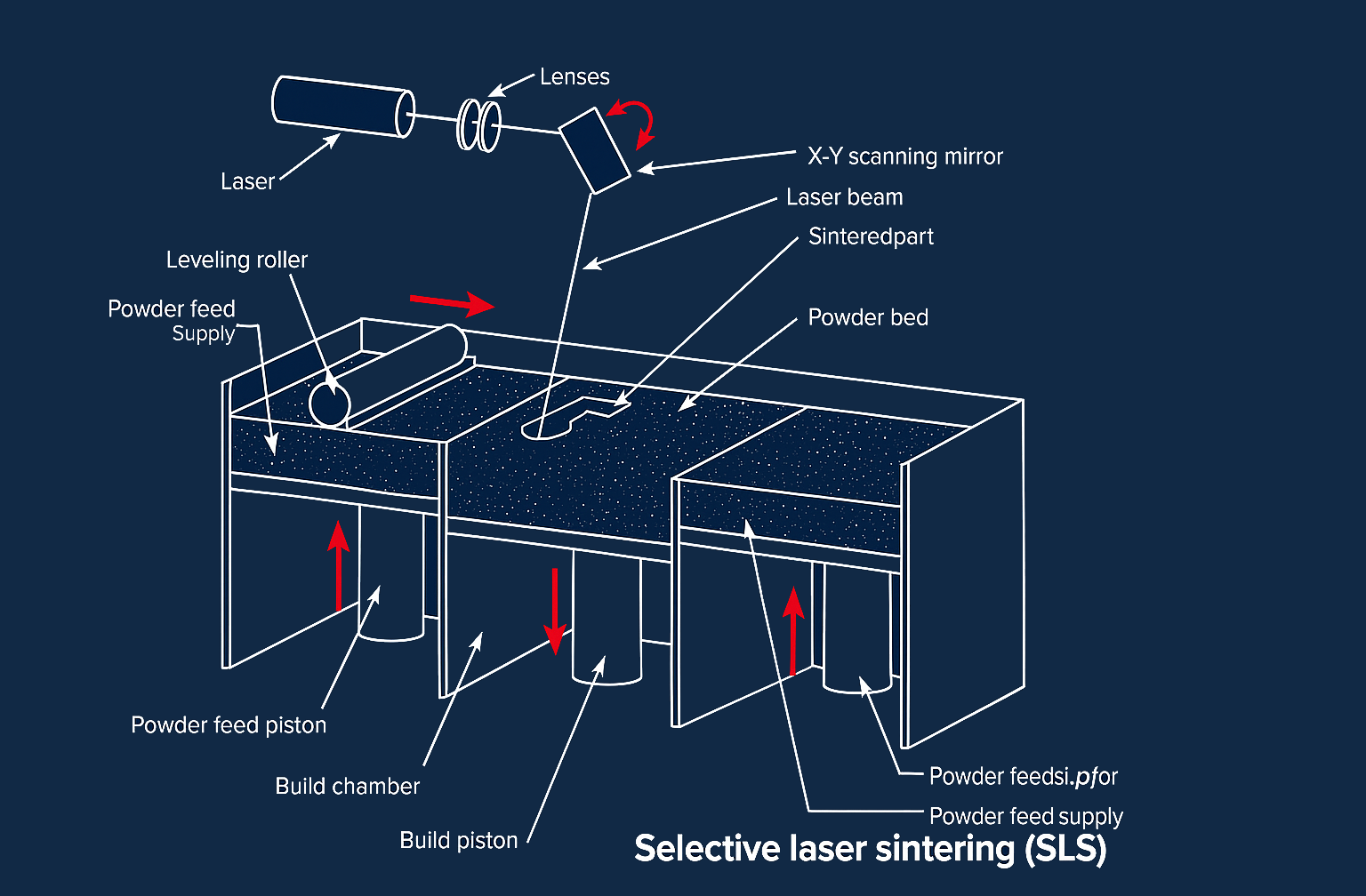
SLS (Selective Laser Sintering):
SLS printing is an advanced manufacturing process that uses high-powered lasers to fuse powdered polymer into a solid part. This technique is one that uses powder bed fusion, where material is deposited layer by layer and fused into the desired part using the high-power laser.
The main advantage to SLS printing over traditional printing is that there is not a need to add printed supports. Instead of printing supports the excess powder acts as a natural support to the part. This allows the printer to produce highly detailed parts with moving components in a single print.
The most common materials used in SLS printing is Nylon 12 and Nylon 11. This is due to the material properties that these types of nylon offer including, flexibility, durability, and Impact resistance. Although nylon is the most common material used SLS supports other thermoplastics such as thermoplastic polyurethane (TPU), which has different material properties to nylon which is why it is used. TPU offers elastic and rubber-like properties making it the choice for flexible parts like gaskets and seals.
Once a print is completed you must clear away the excess powder that is around the part this should be done using a brush or compressed air. After cleaning the part, the part needs to go through a post-processing technique which varies depending on which aspect of the material properties are desired. The most common technique is heating treatment which is used to improve the bond between the material even after the laser sintering. Another technique which is done to improve the finish of the part is to use techniques like sanding, tumbling or chemical smoothing to remove rough textures and create a uniformed finish.
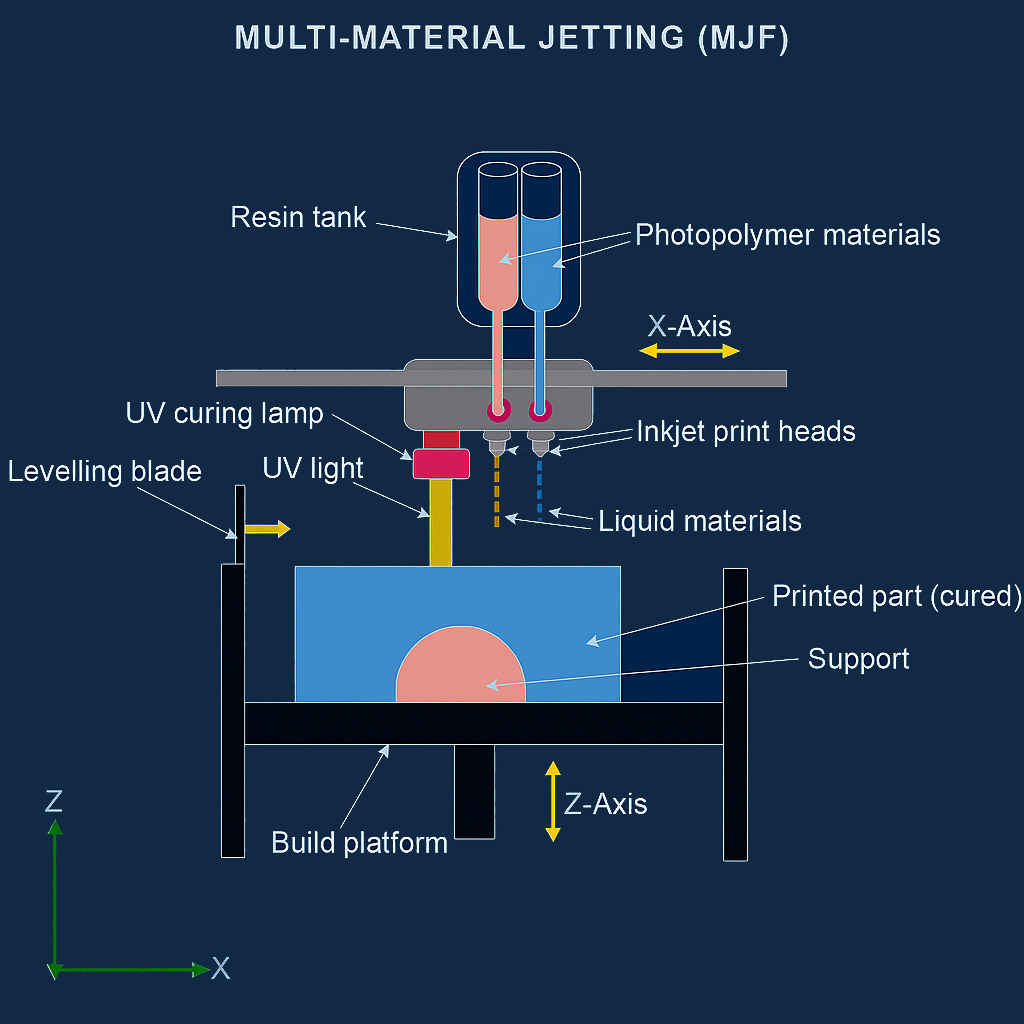
MJF (Multi Jet Fusion):
MJF primarily uses thermoplastic powders with Nylon 12 being the most common material, but other thermoplastics are also used such as TPU. MJF is a printing process that uses an inkjet printhead to deposit, fusing and detailing materials onto a layer of nylon powder. A heated bed is used to initiate the fusing of the materials.
The most recognised advantage of MJF printing is the surface finish of the parts that are produced. The printing process ensures that the components produced also have functional strength and are able to with stand stress while being used.
After a print is produced the post-processing of the print must take place. The first step is to remove any excess powder that may be on the part. This can be done using a brush or compressed air. While MJF is a quick process the surface finish of the parts is quite rough, this can be resolved using solutions like sanding, tumbling and chemical smoothing. Machining can also be used to ensure that the part is within specified tolerances.
Subtractive Manufacturing
Lathe (turning):
Metal lathes are important tools in the production industry for turning down parts, a process that involves rotating a chuck at a high speed while moving a cutting tool along the part. The cutting tool removes material at varying depths, depending on factors such as the type of material and the cutting tool being used.
For example, when using a tungsten carbide-tipped insert tool on aluminium, you can remove up to ⅔rds. of the cutting tools depth as a cut. Using rough cuts, you can quickly take the part down to a smaller size but with a rough finish. Once you have brought it closer to size with rough cuts you would start to take smaller cuts of about 0.5mm to bring the size closer to the final diameter. The final cut to take it to the dimensions of the part to the dimension on a tolerance drawing (BS8888). The depth of cut for a finishing cut is 0.1mm this is done for final dimensions of the part but also to improve the surface finish as rough cuts can leave a visible surface finish.
Securing a material on a lathe is typically done with 3 different devices.
3-Jaw Chuck: A self-centring chuck that is commonly used to hold cylindrical or hexagonal parts. The jaws move simultaneously when they are adjusted, thus making it the choice for quick set ups. However, this chuck is not as versatile and struggles to hold irregular shapes and does not allow for individual jaw adjustment.
4-Jaw Chuck: A chuck that has independent jaw adjustments allowing for flexibility when using irregular shapes. This makes this chuck ideal for tasks that require high accuracy or working with complex shapes. The setup for this chuck is more time consuming than a 3-jaw chuck as it requires the part to be clocked up based on the point you want to be centred.
Faceplate: A faceplate is used to secure large or uniquely shaped material or parts that cannot be secured within a chuck. These parts are secured using bolts, clamps or other fastening devices. Faceplates are best used for machining processes such as, drilling or boring off centre.
- Tools on a lathe are held on a tool post which can hold a varying number of tools depending on the machine being used. These tools can be left on the machine and be zeroed so that when using a tool, it will not need to be set up every time.
- High Speed Steel Cutting Tool - This cutting tool often starts as a bar of high-speed steel that is ground into the desired profile for cutting. The shape of the tool that is ground will vary depending on the material that is being worked on and the process that will be done.
- Insert cutting tool -
- Boring Bar - A boring bar can either be an insert tool or a high-speed steel tool and are used for taking cuts within a previously drilled hole to expand the internal diameter. This could be for a size that cannot be drilled or to make an internal taper.
- Knurling Tool - A knurling tool is used to texture a turned bar. A standard knurling tool will leave a diamond imprint on the bar which is done to increase the grip of a part.
- Under Cut Tool - An under cutting tool is used to take a deep cut into a bar before thread cutting or to add a profile for a rubber gromet or other clasping parts. An undercut tool will come in varying widths and can be both an insert and high-speed steel.
- Parting Off Tool - This tool is used to remove the part from the rest of the bar that is being held in the chuck of the lathe. Usually, you would, if possible, hold out the whole part that you are working on and once you have finished the machining process and the part is within tolerance in accordance with the drawing you would remove it from the bar. This is done by slowly moving this tool into the material bar until it is cut all the way through.
- Thread Cutting Tool - This tool is used to cut a thread into a bar. Using this tool, you would set up the lathe’s auto feed to match the speed of the lathe so that it cuts the thread at the correct pitch in correlation to the thread you are trying to get cut.
- Chamfering Tool – This tool is used to either place the beginning thread onto a bar or to remove burrs and sharp corners to allow it to reduce chance of cutting or scratching other parts.
- Radius Tool (Filleting Tool) – This tool is used to cut a radius onto the edge of a part being made. The size of the radius tool varies but the size of the radius is changed by the setting the depth of the cut before moving the tool into the part.Subtractive Manufacturing
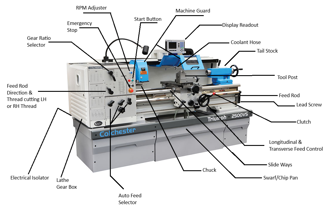
Colchester Triumph 2500VS Lathe Diagram from Colchester - https://www.colchester.co.uk/
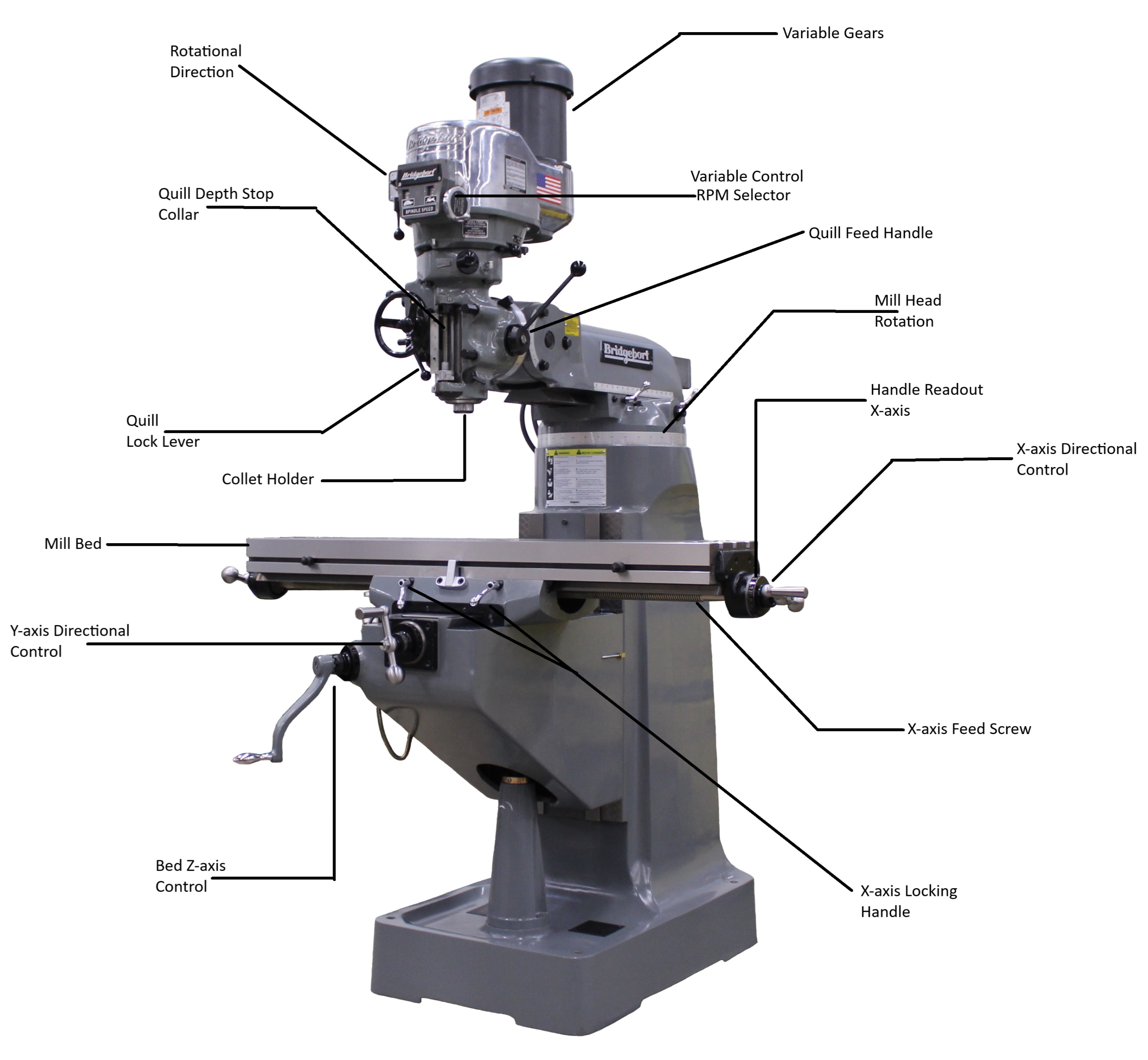
Milling:
A milling machine operates on three fundamental axes of movement, which dictate how the cutting tool interacts with the workpiece.
X-Axis (Lateral Movement) – The X-axis controls the side-to-side motion of the mill bed. The workpiece, whether clamped directly onto the bed or secured within a mounted vice, moves horizontally along this axis.
Y-Axis (Front-to-Back Movement) – The Y-axis controls the movement of the mill bed forward and backward, adjusting the positioning of the workpiece in relation to the cutting tool.
Z-Axis (Vertical Movement) – The Z-axis moves the mill bed up and down relative to the spindle and cutting tool, controlling the depth of the cut.
Different shapes of material require specific clamping techniques to ensure stability and precision during machining:
Block Machining – For solid metal blocks, using a vice is often the preferred method. The vice securely grips the material, minimizing movement and preventing deformation during cutting. If the block were directly clamped to the mill bed, unwanted shifting or inadequate grip could lead to machining errors.
Sheet Metal Machining – Thin sheet materials are best secured directly to the mill bed using clamps. Since a vice provides minimal contact for flat sheet metal, clamping it directly ensures a stable and evenly distributed hold. However, variations in part geometry may require adjustments—complex profiles or delicate structures might benefit from specialized fixtures or sacrificial supports to prevent distortion.
Round Bar Machining – Cylindrical workpieces require additional considerations for stability. Depending on the machining operation, round stock may be held in V-blocks within a vice or secured with custom fixtures to prevent unwanted rotation.
Milling Applications
With control over these three axes, the milling machine enables a variety of machining processes, including:
Face Milling – Flattening or smoothing the surface of a workpiece. This is the first process done to get a block of material ready for later processing.
Edge Milling – otherwise known as peripheral milling, is the process where a cutting tool removes material from the outer edges of the workpiece. Unlike face milling, edge milling is done to shape the material towards the final shape.
Drilling & Boring – Creating holes with precise depth and diameter. This can either be done by using a standard drill bit or using a step drill to size up a hole. Finally, you can use an endmill with centre cutting to plunge into the work piece without having a pilot hole cut into it.
Slotting & Grooving – Carving out slots for functional or decorative purposes.
By understanding the interplay between axis movements and proper workpiece securing techniques, machinists can maximize precision and efficiency in milling operations.
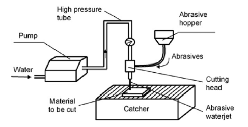
Water Jet Cutting (CNC)
Waterjet cutting uses a high-pressure stream of water, sometimes mixed with abrasive particles like garnet, to precisely cut through various materials, from soft foam to tough metals and stone. The water is forced through a fine nozzle, increasing accuracy and cutting speed. Unlike other cutting methods, it does not generate heat, eliminating material distortion or structural changes. This makes waterjet cutting ideal for industries like aerospace, automotive, and manufacturing, where precision and material integrity are crucial. Additionally, it can manage intricate designs and complex shapes, offering versatility for applications ranging from art and architecture to industrial engineering.
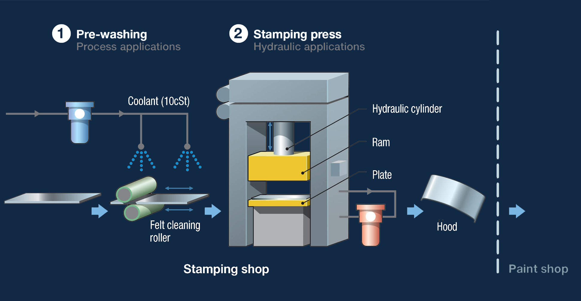
Stamping and Bending
Stamping, also known as pressing, is a cold-forming technique used to shape or cut sheet metal by applying high pressure through a die. This process involves placing the metal sheet onto a die, where a powerful press forces the material into the desired shape. Depending on the design and tooling, stamping can perform various operations, including bending, punching, embossing, or cutting. It is widely used in industries like automotive, aerospace, and manufacturing due to its efficiency in producing high-precision parts at scale. Unlike hot-forming processes, stamping does not require heating the material, preserving its mechanical properties.
Can we help?
Please get in touch if you would like to speak with a member of our Sales team regarding standard or custom parts.
CONTACT SALESRelated posts
-
 Guide to Masking HooksA Complete Guide to Industrial Masking Hooks for Coating, Spraying & Assembly LinesRead more
 -
 Stainless Steel Equivalent GradesCompare stainless steel grades and find the perfect match for your next project.Read more
 -
 Stainless Steel Fasteners: Tightening and Breaking TorquesUnderstanding the Limits: How to Properly Tighten Stainless Steel Fasteners Without Compromising Strength or...Read more
Leave a comment