
Search all blogs
Latest posts
-
 Masking Tape: Uses, Types & How to Choose the Right One27/04/2026Read more
Discover our complete masking tape guide covering die cut, high temp masking tape, automotive and specialist tapes....
-
 Coach Screws Guide: Sizes, Uses and Outdoor Fixing Advice20/04/2026Read more
Complete guide to coach screws, including sizes, timber applications and outdoor fixing advice. Ideal for sleepers,...

Engineering Guide, Screws for Plastic
Table of Contents
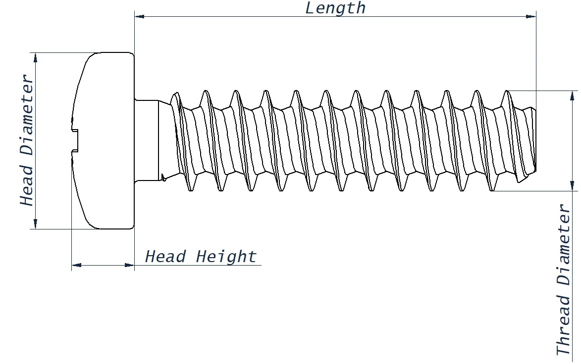
 What makes screws for plastics different from normal screws?
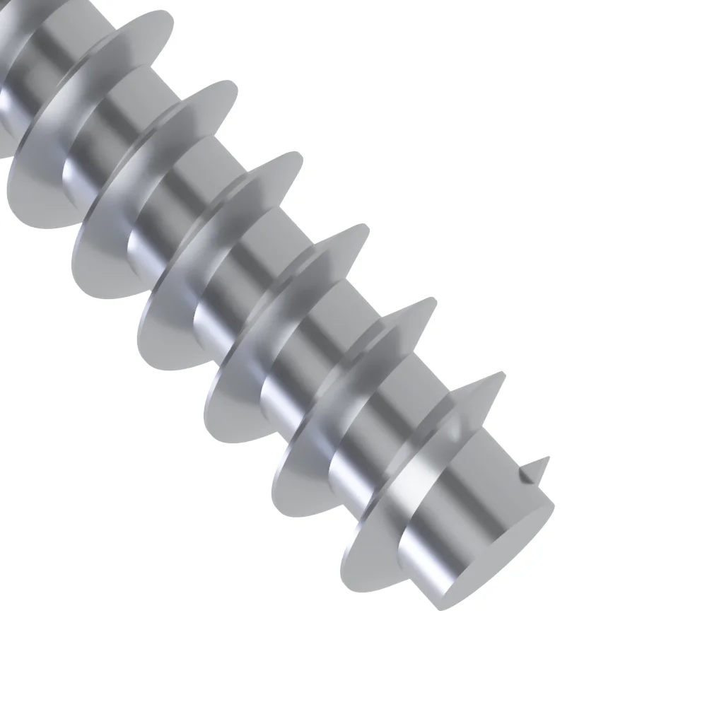
We offer fastener that are designed specifically to be used with plastics, intended for predrilled or moulded in pilot holes. They create threads in plastics by thread forming as opposed to a traditional self tapping screw that cuts into the material:
Thread forming – Where the fastener pushes the material apart into a new shape.
Self tapping – Where the fastener cuts into the material, creating chips and swarf as well as applying more stress to the material.

Why are specialty fasteners for plastics better than standard self tapping screws?
Radial stress needs to be avoided as it can damage or cause cracking in the material.
In the diagram to the right the force applied from the fastener is directed perpendicular to the surface of the thread.
This outward force is reduced by around half as it is proportional to the angle at which it's applied. Where that portion of the force is equal to the sine of the angle on the inclined plane (sin θ).
Sin 15- 0.259
Sin 30 - 0.50
Fasteners for plastics also have a thinner minor diameter and longer threads than standard fasteners.
Below you can see while on major diameter of both screws are the same, due to the smaller minor diameter, there is more material engaged with the fastener it is more resistant to pull out. This is particularly important as plastics tend to be softer.

Most standard self tapping fasteners for woods and metals have a wide flank angle of 60 degrees.
Fasteners for tapping into plastics require narrower flank angles, such as 30 or 45 degrees. This reduces radial stress and expansion when the fastener is driven into the material. When these are reduced it allows for boss used to also be reduced. Bringing wall thicknesses down in plastic moulding allows for reduction in cost as less material is used and cycle time can be increased.
In the diagram to the left, you can see the 30 degree thread profile allows with the same amount of displacement in the material, a deeper thread that engages with more material.
How do I reduce creep when fastening plastics?
Under load or heat plastics can be susceptible to creep, a slow permanent deformation of the material. This will reduce overall clamping load.
In your design this can be compensated by:
- Using a wider diameter head, such as our flanged head fasteners.
- Adding a flat washer to spread load
- Adding a spring element, such as a coiled or curved washer, to compensate for movement in the assembly.
- Reduce diameter of the clearance hole.
- Adding a compression limiter or metal sleeve to the clamped component.
- Using a stiffer plastic.
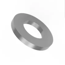
Flat Washer
Flat washers can spread load over a wider area in a fastening assembly.
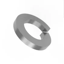
DIN127B Spring Washer
Spring elements such as DIN127B washers can compensate for creep in your assembly.
What torque do I used for fasteners for plastics?
Identifying the correct torque requirement is important as these can vary depending on the fasteners, as longer screws generally require more torque, as well as plastics having a wide variety of properties and hardnesses.
As a general recommendation we advise:
- Secure enough samples to have a statistically relevant sample size, usually 30 or more for a specific assembly should suffice.
This should include all components in the assembly, such as the fastener, clamped components and any additional items such as washers. - Ensure the driver used in the test can drive the fastener to failure.
Use a driver that operates at the same speed and power in both testing and production. - Using a device that can measure torque, drive the fasteners to failure and take an average of:
Peak torque – The point at which the torque increases as the two materials are drawn together.
Ultimate torque – The maximum value before the assembly fails, usually when the threads strip. - Calculate the average value of the of the peak torque and ultimate torque, this should provide a value where the torque is high enough to seat the fastener correctly but comfortably below the ultimate torque value.
Factor in ±10% accuracy on the driver. This should have a good range of values for your torque setting.
Should I use 30 degree or 45 degree screws?
We offer two types of thread on our fasteners. The key difference between them is the threads on the 30 degree screws are longer and sharper. Where as 45 degree screws have a shorter but trilobular thread

30 degree thread form - PT30
- Provides good performance in the majority of plastics.
- Greatest reduction on radial stress on the displaced material due to sharp flank angle.
- Able to be installed into thinner bosses due to reduced radial stress.
- Lowest installion torque.
45 degree thread form - PT45
- Middle ground between a 30 degree screw and a regular self tapping screw
- Trilobular body and shorter threads better for cutting into harder materials, such as glass reinforced plastics.
- High drive to strip ratio.
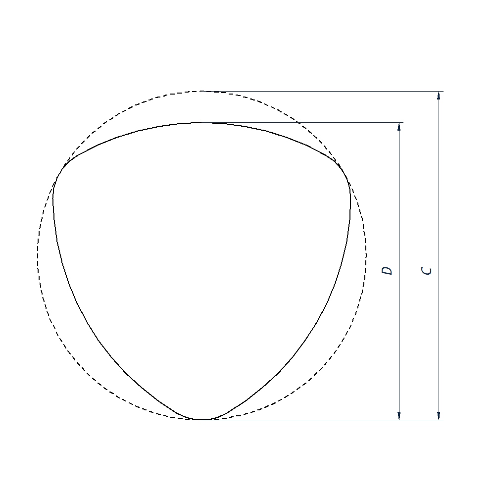
What are trilobular screws?
Trilobular threads on fasteners can be identified by having 3 sides. Despite appearance the width through the centre is constant at any point across the thread.
This design allows thread forming by pushing material aside rather than cutting into the material, and it allows this at a lower torque than if the thread was round. This is achieved by concentrating the force at those points.
The below diagram is exaggerated and the exact values for the screw diameter and the outer circle diameter are on the tolerance charts at the bottom of the page.
As such, as a starting point please reference to the Flexural Modulus of the plastic, we have some indicative values below but it can vary from grade to grade, even on the same base plastic.
| Recommended Screw | Material Code | Full Material Name | Flexural Modulus (PSI) |
Flexural Modulus (MPa) |
|
| Soft | PT 30 | LDPE | Low Density Polyethylene | 150,000 | 1,000 |
| PP | Polypropylene | 200,000 | 1,400 | ||
| PC | Polycarbonate | 340,000 | 2,300 | ||
| ABS | Acrylonitrile butadiene styrene | 350,000 | 2,350 | ||
| PA 66 | Nylon 6/6 | 350,000 | 2,350 | ||
| POM | Acetal / Polyoxymethylene | 400,000 | 2,700 | ||
| PS | Polystyrene | 430,000 | 2,900 | ||
| PP TV20 | Polypropylene - 20% Talc Filled | 500,000 | 3,300 | ||
| PPS | Polypheylene Sulfide | 550,000 | 3,700 | ||
| Moderate |
PT30 / PT45 |
ABS GF20 | Acrylonitrile butadiene styrene - 20% Glass Filled | 650,000 | 4,300 |
| PA 66 GF12 | Nylon 66 - 12% Glass Filled | 800,000 | 5,300 | ||
| PC GF20 | Polycarbonate - 20% Glass Filled | 850,000 | 5,700 | ||
| Stiff | PC GF30 | Polycarbonate - 30% Glass Filled | 1,100,000 | 7,300 | |
| PBT GF30 | Polybutylene terephthalate - 30% Glass Filled | 1,100,000 | 7,300 | ||
| PA66 GF30 | Nylon 6/6 - 30% Glass Filled | 1,200,000 | 8,000 | ||
What are materials and head styles are available?
Our screws for plastics are all available in three materials.
- Bright Zinc plated Steel – This is the most commonly used and standard finish as it’s economical and suitable for the majority of applications, featuring a bright metallic silver colour.
- Black Zinc Plated Steel – This finish is mechanically identical to the silver colour zinc.
They are commonly used for their aesthetic purposes, in industries such as automotive interiors, PC or computer server building or retail displays. - A2 Stainless Steel – This material has the highest corrosion resistance, usable in industries such as petrol / chemical applications, outdoor applications as well as food / catering.

Bright Zinc Plated
A common silver colour coating on case hardened steel.
Black Zinc Plated
Mechanically identical to bright zinc plated, but offering a different aethetic finish.
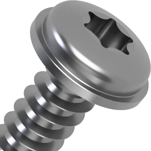
A2 Stainless Steel
The most corrosion resistant material available.

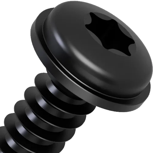
Torx Drive
This drive, also known as kaxalobular, offers the best torque transfer.
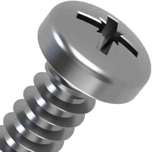
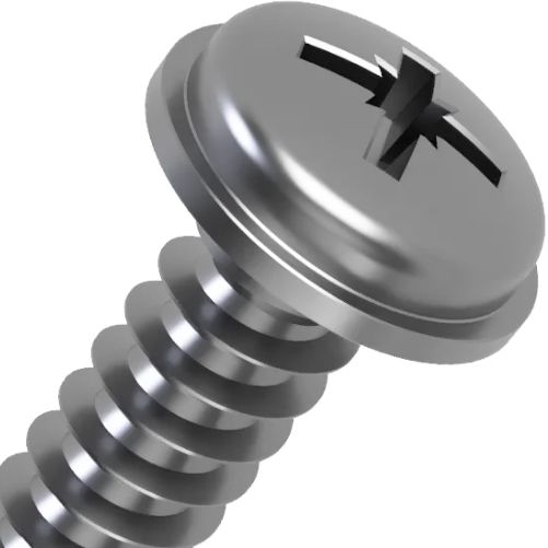
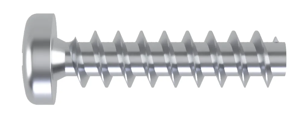
Pan Head
This is our most common head, suitable for a wide range of implementations.
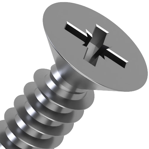
Countersunk
This head style allows for the surface of the screw head to be flush against the surface of the panel.
Flanged Head
This is the widest head we offer, the wider head is better as spreading stress over a wider area, particularly of relevance when working with softer plastics.
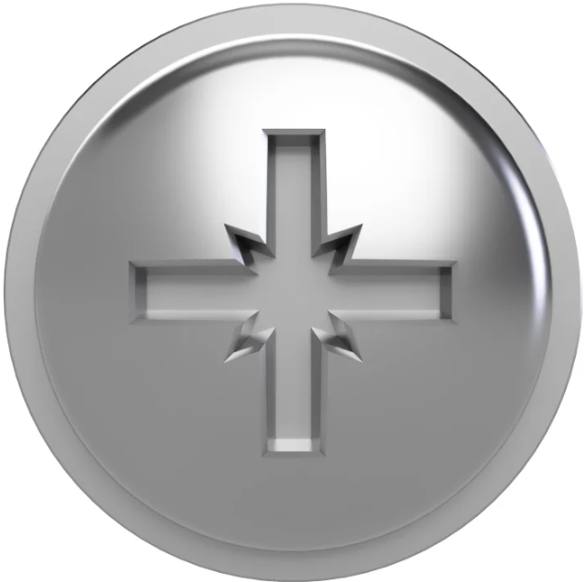
Pozi Drive
This is the most commonly and readily available drive.
Drive Types
Every fastener we can provide is available with these three head styles.
- Pan head – This is our most common head, suitable for a wide range of implementations.
- Countersunk – This head style allows for the surface of the screw head to be flush against the surface of the panel.
- Flanged – This is the widest head we offer, the wider head is better as spreading stress over a wider area, particularly of relevance when working with softer plastics.
Those three head styles above are all available with both Pozi or Torx drives
- Pozi – Similar in appearance to the Philips design but allowing for more torque transfer before the driver cams out compared to Philips.
This is a driver where the tools are commonly used and readily available. - Torx – This drive offers the best performance, with a high contact area. Where a Pozi screwdriver is pointed a torx driver is closer to having 90 degree sides.
This performance difference is particular noteworthy when the fastener is used in automation or fastened robotically. However the disadvantage is the around tool availability as Torx drives come in more sizes.
How do I design bosses for fasteners for plastics?
Due the different thread forms and different properties of various plastics, the recommended hole sizes are below.
We also recommend the general considerations with all shapes and styles of fastener;
- For best results, chamfer the leading edge on the pilot hole. Preferably to the nominal diameter of the screw.
- The recommended length of engagement is a minimum of 2-3 times the diameter of the screw. Not including the leading thread, the first twist, as this is tapered.
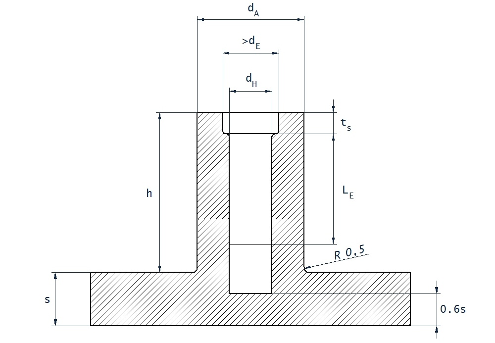
| d | Nominal Screw Diameter |
| dA | Boss Diameter |
| dH | Hole Size |
| ts | 0.4 x d |
| h | Minimum - LE + (1 x d) |
| LE | Length of Thread Engagement |
| S | No specific value |
Boss Sizing Chart - PT30 Screws
Material Code |
Full Material Name |
Hole Size (dH) |
Boss Diameter (dA) |
Thread Engagement (LE) |
| ABS | Acrylonitrile butadiene styrene | 0.80 x d | 2.00 x d | 2.00 x d |
| ABS/PC Blend | Acrylonitrile butadiene styrene + Polycarbonate | 0.80 x d | 2.00 x d | 2.00 x d |
| ASA | Acrylonitrile styrene acrylate | 0.78 x d | 2.00 x d | 2.00 x d |
| PA 46 | Nylon 4/6 | 0.73 x d | 1.85 x d | 1.80 x d |
| PA 46 GF30 | Nylon 4/6 - 30% Glass Filled | 0.80 x d | 1.85 x d | 1.80 x d |
| PA 6 | Nylon 6 | 0.75 x d | 1.85 x d | 1.70 x d |
| PA 6 GF30 | Nylon 6 - 30% Glass Filled | 0.80 x d | 2.00 x d | 1.90 x d |
| PA 66 | Nylon 6/6 | 0.75 x d | 1.85 x d | 1.70 x d |
| PA 66 GF30 | Nylon 6/6 - 30% Glass Filled | 0.82 x d | 2.00 x d | 1.80 x d |
| PBT | Polybutylene terephthalate | 0.75 x d | 1.85 x d | 1.70 x d |
| PBT GF 30 | Polybutylene terephthalate - 30% Glass Filled | 0.75 x d | 1.85 x d | 1.70 x d |
| PC | Polycarbonate | 0.85 x d | 2.50 x d | 2.20 x d |
| PC GF30 | Polycarbonate - 30% Glass Filled | 0.85 x d | 2.20 x d | 2.00 x d |
| LDPE | Low density Polyethylene | 0.70 x d | 2.00 x d | 2.00 x d |
| HDPE | High density Polyethylene | 0.75 x d | 1.80 x d | 1.80 x d |
| PET | Polyethylene Terephthalate | 0.75 x d | 1.85 x d | 1.70 x d |
| PET GF 30 | Polyethylene Terephthalate - 30% Glass Filled | 0.80 x d | 1.80 x d | 1.70 x d |
| PMMA | Methyl Methacrylate | 0.85 x d | 2.00 x d | 2.00 x d |
| POM | Acetal / Polyoxymethylene | 0.75 x d | 1.85 x d | 2.00 x d |
| POM GF30 | Acetal / Polyoxymethylene - 30% Glass Filled | 0.80 x d | 1.85 x d | 2.00 x d |
| PP | Polypropylene | 0.70 x d | 2.00 x d | 2.00 x d |
| PP GF30 | Polypropylene - 30% Glass Filled | 0.72 x d | 2.00 x d | 2.00 x d |
| PP TV20 | Polypropylene - 20% Talc Filled | 0.72 x d | 2.00 x d | 2.00 x d |
| PPO | p-phenylene oxide | 0.85 x d | 2.50 x d | 2.20 x d |
| PS | Polystyrene | 0.80 x d | 2.00 x d | 2.00 x d |
| PVC (Rigid) | Polyvinyl Chloride | 0.80 x d | 2.00 x d | 2.00 x d |
| PEEK | Polyether Ether Ketone | 0.85 x d | 2.00 x d | 2.00 x d |
| Screw Diameter | Soft Materials | Hard Materials |
| 1.8 | 1.19 | 1.45 |
| 2.2 | 1.47 | 1.79 |
| 2.5 | 1.80 | 2.00 |
| 3.0 | 2.26 | 2.50 |
| 3.5 | 2.73 | 2.95 |
| 4.0 | 3.18 | 3.41 |
| 5.0 | 3.62 | 4.10 |
| 6.0 | 4.55 | 5.05 |
Boss Sizing Chart - PT45 Screws
As a general rule we recommend as a beginning point;
- The diameter of the boss should be at least 2.5 to 3 times the diameter of the screw.
- We recommend the hole sizes in the right hand table, this can be increased by approximately 10% to accommodate longer screws and reduce required torque.
Typical Soft plastics include LDPE, PP, ABS and Nylons.
Typical Hard plastics include Polycarbonate, glass or otherwise reinforced plastics.
Tolerance Infomation
and size charts
PT30 Screws

Tolerance Chart - Diameters
| Size | Pitch | d (Min) | d (Max) | d1 |
| 1.8 | 0.8 | 1.80 | 1.90 | 1.04 |
| 2.2 | 0.98 | 2.20 | 2.34 | 1.25 |
| 2.5 | 1.12 | 2.50 | 2.64 | 1.40 |
| 3.0 | 1.34 | 3.00 | 3.15 | 1.66 |
| 3.5 | 1.57 | 3.50 | 3.68 | 1.91 |
| 4.0 | 1.79 | 4.00 | 4.18 | 2.17 |
| 5.0 | 2.24 | 5.00 | 5.20 | 2.68 |
| 6.0 | 2.69 | 6.00 | 6.20 | 3.19 |
Tolerance Chart - Length
| Nominal Length | Tolerance (mm) |
| 4 - 6 | ±0.60 |
| 7 - 10 | ±0.75 |
| 12 - 18 | ±0.90 |
| 20 - 30 | ±1.05 |
| 35 - 50 | ±1.25 |
| 60 | ±1.50 |
Tolerance Infomation
and size charts
PT45 Screws

Tolerance Chart - Diameters
| | C Hole Diameter |
D Screw Diameter |
|||
| Size | Pitch | Min | Max | Min | Max |
| 1.8 | 0.8 | 1.75 | 1.85 | 1.65 | 1.75 |
| 2.2 | 1.0 | 2.15 | 2.25 | 2.05 | 2.15 |
| 2.5 | 1.4 | 2.45 | 2.55 | 2.40 | 2.50 |
| 3.0 | 1.5 | 2.95 | 3.05 | 2.90 | 3.00 |
| 3.5 | 1.65 | 3.45 | 3.55 | 3.37 | 3.47 |
| 4.0 | 1.75 | 3.91 | 4.06 | 3.81 | 3.96 |
| 5.0 | 2.3 | 4.91 | 5.06 | 4.81 | 4.96 |
| 6.0 | 2.5 | 5.91 | 6.06 | 5.80 | 5.85 |
Tolerance Chart - Length
| Size | Length | Tolerance |
| 1.8 - 2.2 | Any | ±0.8mm |
| 2.5 - 5.0 | < 20 mm | ±0.8mm |
| > 20 mm | ±1.3mm | |
| 6 + | Any | ±1.3mm |
Pilot Hole Diameter
| Size | Soft Plastics | Hard Plastics |
| 1.8 | 1.19 | 1.45 |
| 2.2 | 1.47 | 1.79 |
| 2.5 | 1.80 | 2.00 |
| 3.0 | 2.26 | 2.50 |
| 3.5 | 2.73 | 2.95 |
| 4.0 | 3.18 | 3.41 |
| 5.0 | 3.62 | 4.10 |
| 6.0 | 4.55 | 5.05 |
Require any Further help?


Related posts
-
 Guide to EPDM CapsWhat Are EPDM Caps? Key Applications, Advantages, and Installation TipsRead more
 -
 Guide to Masking HooksA Complete Guide to Industrial Masking Hooks for Coating, Spraying & Assembly LinesRead more
 -
 The Complete Guide to Wing nutsEverything you need to know about wing nuts: uses, types, and expert tips for every project.Read more
Leave a comment